Ensuring quality with the most advanced measurement and analysis equipment
There are many small metal parts that our manufacturing company Micro MIM Group produces using µ-MIM® technology that are difficult to mass-produce by machining, such as free-form surfaces, complex hollow structures and gears. Even these difficult to standardize components, are properly evaluated and quality assured.
Optical 3D measuring system
Micro MIM Group uses the ATOS Triple Scan System from GOM, Germany. In cooperation with the development team, the Micro Focus model was introduced for the first time in Japan.
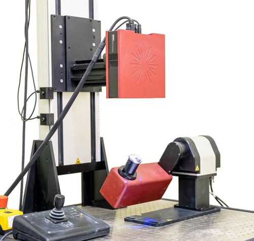
ATOS triple scan
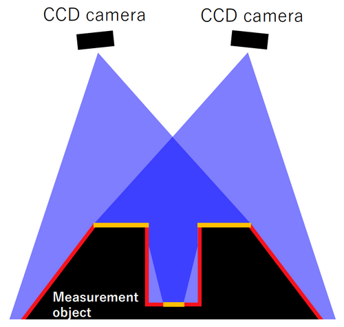
Scan pattern diagram
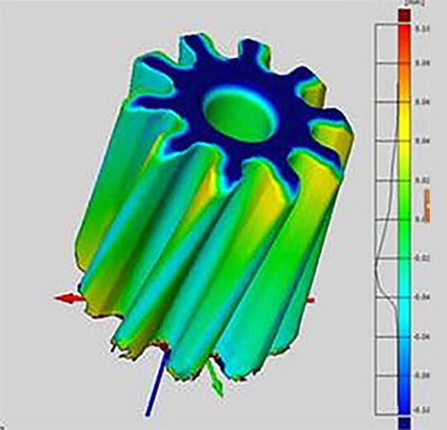
Profile model
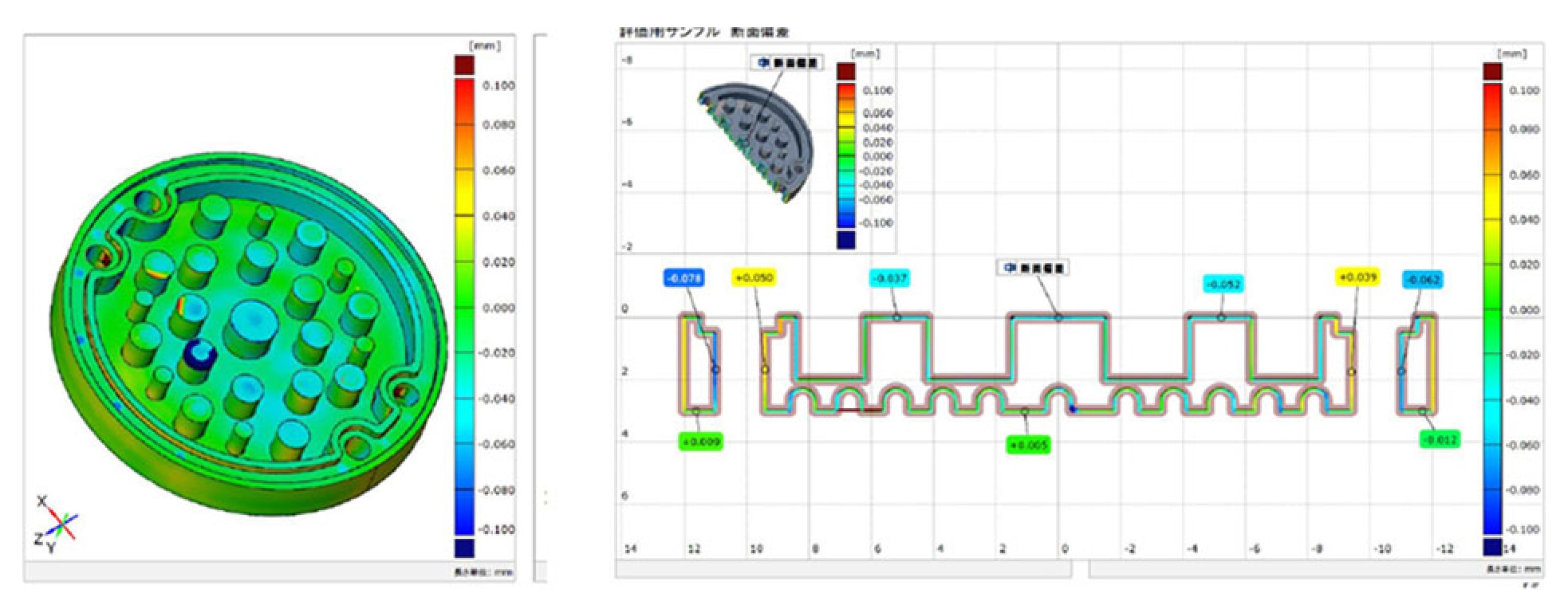
Profile model

Confetti
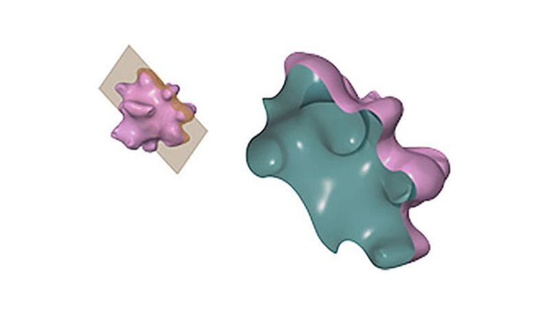
3D CAD model of confetti
X-ray CT
Micro MIM Group uses the MCT225, a Nikon Corporation CT measurement system for measuring components with complex internal shapes. It enables non-destructive evaluation of external and internal 3D structures in single micron resolution. In addition, cross-sectional views of any location, comparative analysis with CAD data and dimensional analysis are possible.
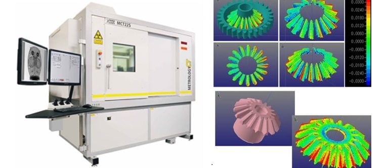

Data analysis technology
We can measure shapes that cannot be measured with other measuring devices, such as internal gears with an outer diameter of a few millimeters or less. In combination with newly developed gear evaluation software, it is possible to certify a grade according to gear standards.
Measurement example confetti
Non-destructive and high-precision evaluation is possible for any shape
3D data can be obtained even from difficult shapes.

Example confetti
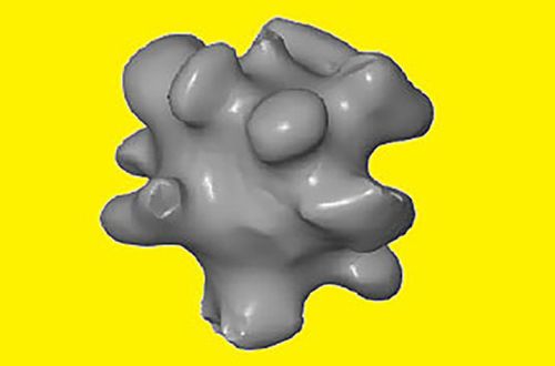
Graphic of confetti created by ATOS
3D-model movie of confetti by ATOS
Measurement example check valve
Evaluationg the internal structure of microcomponents
It can also measure the internal structure of minute components.
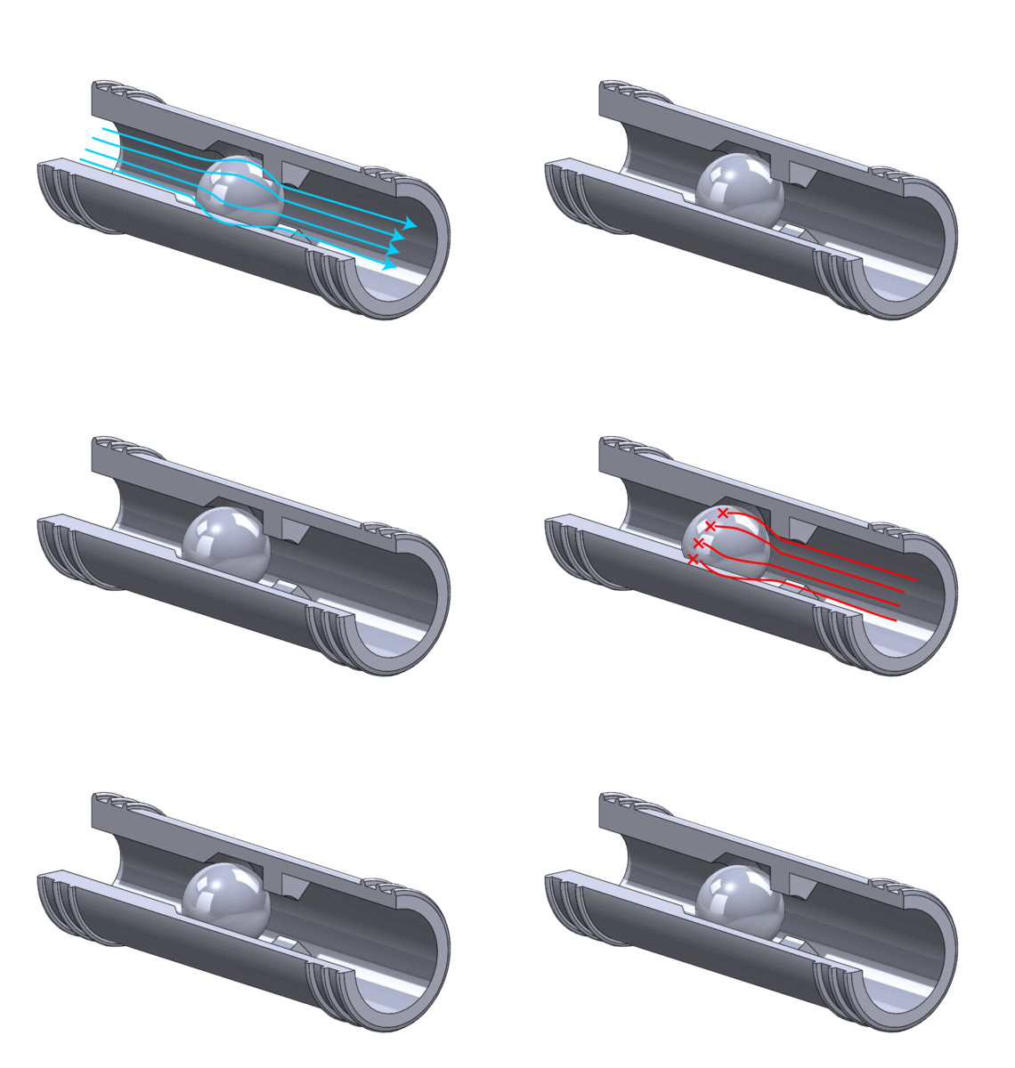
Micro check valve
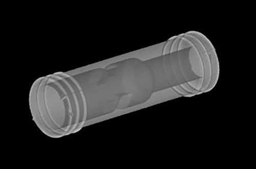
Inside of the component by CT-scanner
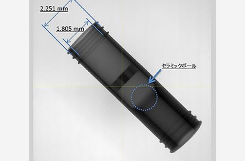
Dimensions of component
CAD data
Comparative verification to the CAD data
We guarantee ±0.01mm tolerance range (with a component's dimension < 5mm), such as a small nozzle, free curved parts, and so on.
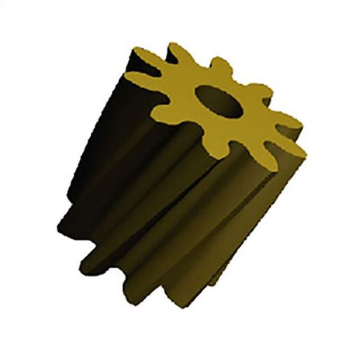
CAD data
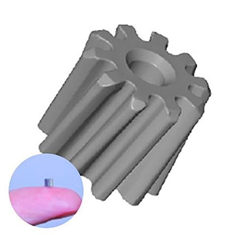
3D SCAN
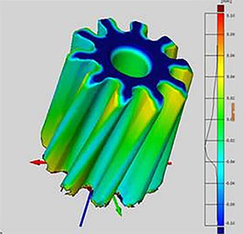
Comparison
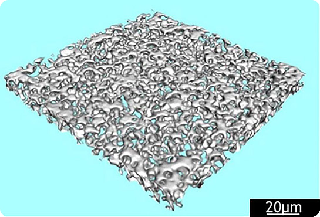
Gathering 3D data of components non-destructively
We can obtain external and internal 3D data of components non-destructively.
We can also measure porous materials, for instance, we can analyse porosity, pore cross-section and more.
Calculating the void volume, a statistical summary of the cross-sectional volume and the average diameter of the porous hole are possible.
Analysing gears
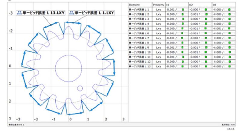
We can also evaluate the pitch error, tooth thickness, tooth type/track error, tooth surface error, quality certification (DIN, AGMA, JIS), etc.
Measurement ability: focus on a point of 3μm
Dimensional precision: 9+L/50μm
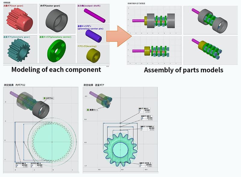
Assembly simulation
By comparing the measured data and the original 3D CAD data, we can simulate the assembly or movement as well as the gear contact and its movement.
Simulating gear engagement in products
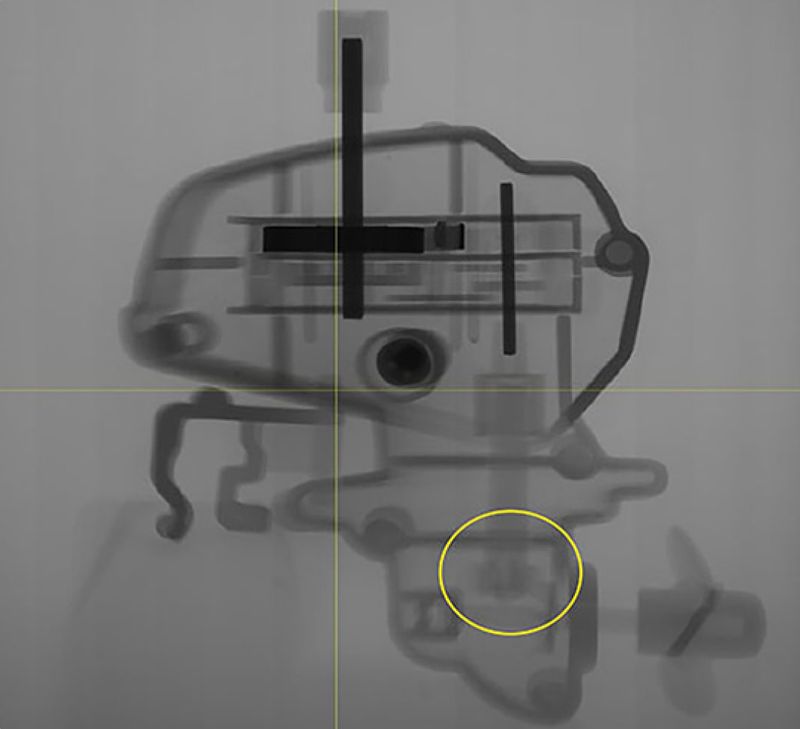
Applicable for measurement and evaluation of installed gears in the components shown.
Here you can see a measurement image made by a Xray-CT of gears in the products.
Schedule a free initial consultation with one of our experts
We will gladly answer your open questions and show you how we can help you solve your technical challenges.
